CAD~CAM~CNC for Vectorworks® |
$20.00
This product requires VectorWorks 2008 or above.
For information on how to install plug-ins for Vectorworks, please see the VectorWiki article entitled Installing Plug-ins.
The Export Plasma Path command will export the G-code necessary to cut parts out of sheet stock using a plasma cutter. The proper entry and exit moves will be inserted to prevent stop/start marks in the work, and the cutter stream will be turned on and off at the appropriate times.
After the G-code has been written to the output file, the file is automatically read back in, and the tool path is drawn so that the moves can be double-checked visually before running the part program on the machine.
All of the cutting will be done with the left shoulder of the plasma stream. In other words, holes will always be cut in a clockwise direction, and the perimeter of parts will always be cut in a counter-clockwise direction.
To prepare the drawing for exporting G-code, you should:
- Draw the parts that you want to cut using the true dimensions. The exported G-code will use cutter compensation commands to account for the width of the plasma stream.
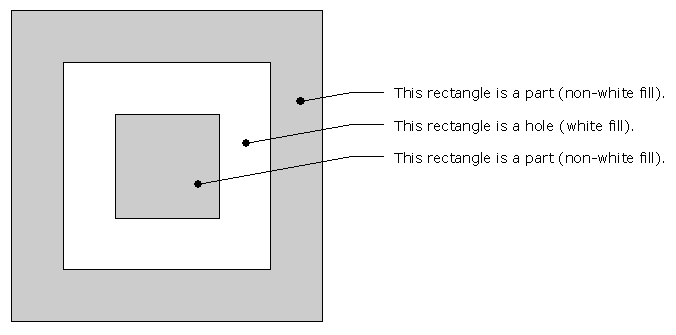
- Draw the parts and holes using fully-closed shapes. These can be rectangles, polygons, polylines, circles, ovals, or rounded rectangles.
- Set the fill color of all objects representing holes to white, and the color of all parts to anything but white.
- In addition to doing parts and holes, you can also do slits, where the cutter will simply follow the path that is drawn, with no faring-in or faring-out moves, and with no cutter compensation. These have to be drawn as open shapes, and supported object types include lines, arcs, open polygons, and open polylines. Open shapes can also be drawn to define parts or holes, in situations where the automatically-generated entry/exit moves are not desired. Just remember that cutter comp commands will not be written for these moves, so these will have to be manually added to the output file, or you should manually offset the open shapes to achieve the desired cutter comp without using G4x commands in the part program.
To export the G-code, click the Export Plasma Path command, and then pick the shapes in the order in which you want them cut. If you are cutting nested parts, where you're getting one part out of the scrap from a hole in another part, then obviously the inner part should be cut first, before the hole in the outer part is cut.
As you pick shapes to be cut, they are hidden from view, as a visual indication that they have been picked, and so that you don't have to remember what you've already picked and what you haven't. All of the objects will re-appear after the command completes.
To define where the entry/exit moves will occur, pick the shape to be cut on the edge where the entry/exit moves should be made. The segment picked will automatically be sub-divided, and the entry/exit point will be at the center of the picked segment.
When picking a slit, pick the object at the end of the slit where the cut should start.
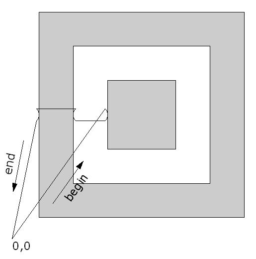
The parts shown above generated the following code:
(CAD File: Test.vwx)
(Sunday, April 20, 2008  5:33:49 PM)
(This part program assumes...)
(   EDIT/EIA/#FORMAT Numeric Format = FLOATING)
(   EDIT/EIA/#FORMAT I&J Codes in Abs.Mode = NO)

N1 G20
N2 G90
N3 M08
N4 G40
N5 G00 X2.677 Y3.752
N6 G42
N7 M07
N8 G02 X2.750 Y3.575 I-0.177 J-0.177
N9 G01 X2.750 Y2.588
N10 G01 X4.725 Y2.588
N11 G01 X4.725 Y4.563
N12 G01 X2.750 Y4.563
N13 G01 X2.750 Y3.575
N14 G02 X2.677 Y3.399 I-0.250 J0.000
N15 M08
N16 G40
N17 G00 X1.836 Y3.399
N18 G42
N19 M07
N20 G02 X1.762 Y3.575 I0.177 J0.177
N21 G01 X1.762 Y5.551
N22 G01 X5.713 Y5.551
N23 G01 X5.713 Y1.600
N24 G01 X1.762 Y1.600
N25 G01 X1.762 Y3.575
N26 G02 X1.836 Y3.752 I0.250 J0.000
N27 M08
N28 G40
N29 G00 X0.701 Y3.752
N30 G42
N31 M07
N32 G02 X0.775 Y3.575 I-0.177 J-0.177
N33 G01 X0.775 Y0.612
N34 G01 X6.701 Y0.612
N35 G01 X6.701 Y6.538
N36 G01 X0.775 Y6.538
N37 G01 X0.775 Y3.575
N38 G02 X0.701 Y3.399 I-0.250 J0.000
N39 M08
N40 G40
N41 G00 X0 Y0
N42 M02
N43 %